Lack of space was quite apparent so a plan had to be put in place. The car shops were occupying valuable land and would have to be relocated. It was decided to install a new spur for the car shops next to the two stall engine shed. Existing scenery was removed and the concrete floor pad was poured at the new location seen in the picture to the right of the engine house foundation.
Changing Times
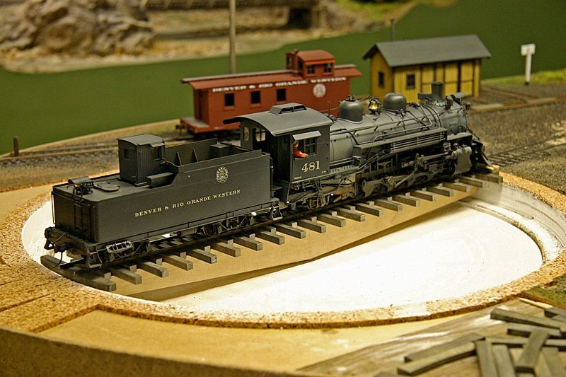
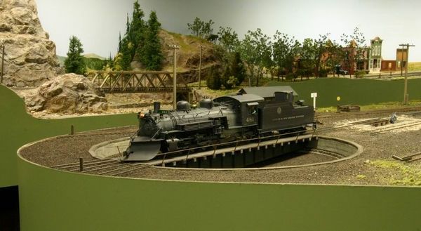
After many years of operation with small locomotives, the D&RGW acquired a K-36 Class 2-8-2. The common practice of running the C-16 Class 2-8-0’s in reverse when returning from Sonjora to Rio Yard was not an option that could be applied to the K-36 Class loco. The time had come to expropriate some real estate and construct a turntable for Rio Yard.
Relocating the Car Shops
The New Plan
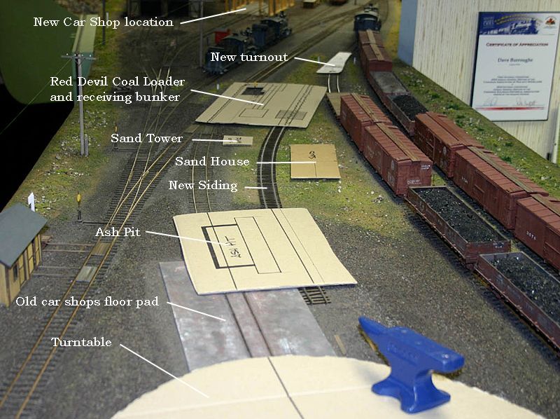
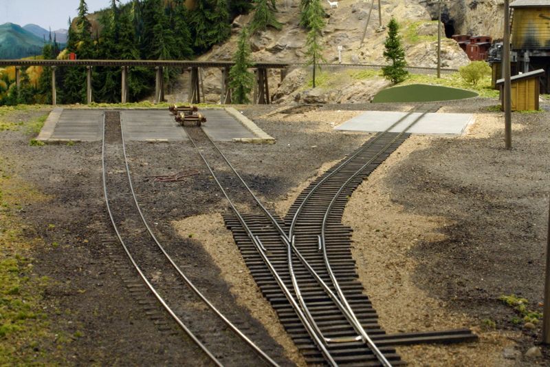
The old car shop siding would serve as a lead to the new turntable. On this same track would be an ash pit and a sand facility and coaling. The sand pit, ash pit and coal facility would need to be serviced. A siding was taken off the south storage track in Rio Yard which would run over a coal receiving bunker, behind the sand house and bin to the ash pit. This added three set off locations for freight cars and enhanced operation.
To make room for the new turntable, it was obvious that the existing tabletop was not large enough. The end of the tabletop had to be extended but that would be at the expense of aisle space. A few years ago, the entrance into the main layout area was widened in anticipation of an extension for a turntable. By sinking half of the new turntable into the existing bench work, a 12″ addition was all that was needed to accomodate the turntable.
Turntable
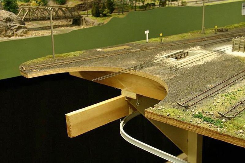
Construction began with removal of the fascia and the cutting of the semi-circle where the turntable was being half recessed into the end of the existing tabletop. The original L-girders had to be cut back and new L-girders installed which would support the turntable assembly. The picture below shows the fascia removed, semi circle cut and the new L-girders installed. The ash pit and new service track are visible in this view.
MDF (medium density fibreboard) was chosen for use in fabrication of the pit. MDF is more stable than plywood and would retain it’s dimensions with the changes in temperature and humidity in the train room. The only concern was to prevent water soaking into the MDF during scenicing and plaster operations. In my case, a good friend facilitated having the MDF laminated and cut on a CNC machine which made for a dimensionally perfect pit assembly. One could easily use a router with a circle cutter, band saw or sabre saw to cut the circles out of the MDF material.
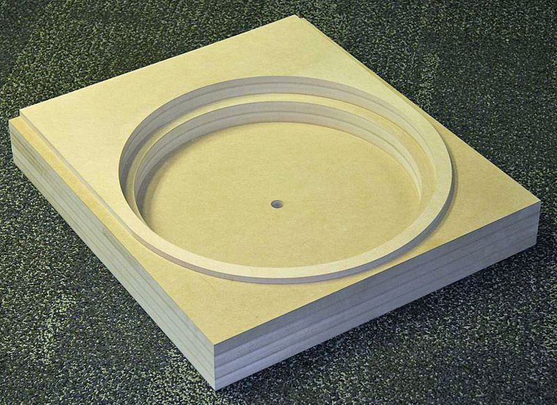
My assembly was designed to fit below the existing tabletop and expose a 3/4″ ring around the circumference. The rest of the assembly sits on the L-girders and was fastened in place once all fine adjustments had been made.
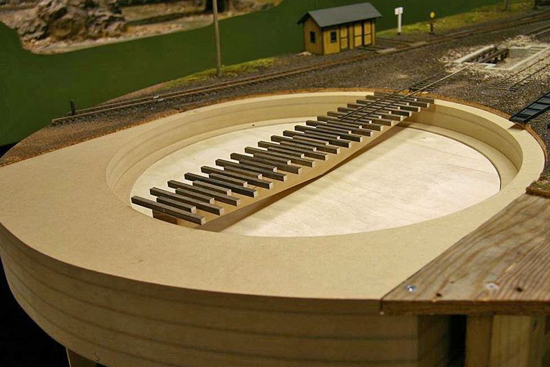
The next item to construct was the turntable bridge. The bridge was cut from well cured maple and spins on a 1/2″ steel shaft supported by two self-aligning bearings. The bridge will be covered with pre-painted and weathered styrene girders at a later time. Once the bridge was cut to size, a hole was carefully bored to take a 1/2″ steel shaft with a keyway. The bridge and shaft assembly was now inserted into the bearings and aligned. With the mounting carriage bolts finger tight, the upper bearing was tapped with a small hammer until the bridge was centred in the pit opening. Then the bottom bearing was tapped until the table was perfectly level for a full rotation.
The machine screw in the picture below is used for fine adjustment of the height of the table. Once everything was satisfactory, all bearing mounting bolts were tightened. Cross ties and rails were installed on the maple bridge and finely aligned.
The next step was to plaster the pit walls and floor. A profile gauge made from .060 styrene was used to ensure the pit was symmetrical. Plaster of Paris was used and wiped around the pit walls with a finger then using the form cut which pivoted
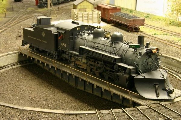
around a spare piece of centre shaft material. The gauge was used to contour the pit walls and then the pit floor. Care was taken to prevent plaster and moisture from going down the centre hole and damaging the bearings by packing the hole with paper towel. The pit walls were carved to simulate cracks in the cement wall before the plaster cured. Perfection was not striven for on the pit walls giving the concrete an appearance of deterioration. Once dry, the pit walls were stained with washes of paint and stain to appear cracked and weathered. The pit ring timbers were now cut, contoured and stained before fitting in place. Ties and rail were installed up to the edge of the pit and the scenery was patched in at the same time as the pit floor was covered. Pit ties and the ring rail were installed to complete the pit. At this time, the pre-painted styrene bridge girders were installed. Final alignment of the turntable rails to the approach track was performed. The time had come to add the deck timbers and hand rails.
Drive Mechanism and Powering
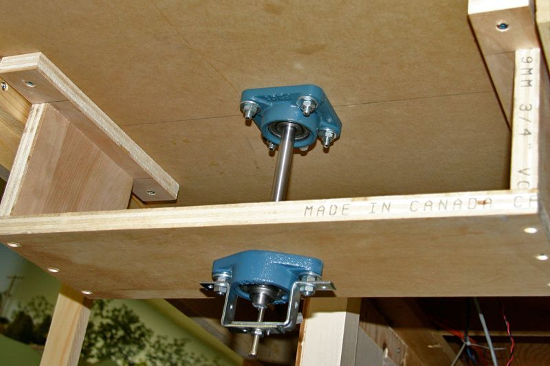
The turntable is driven with a Switchmaster motor and rubber capstan against a 12″ diameter particle board disk. The Switchmaster is run through a Digitrax decoder so any throttle can operate the turntable without having to go to a control panel and turn a rheostat.
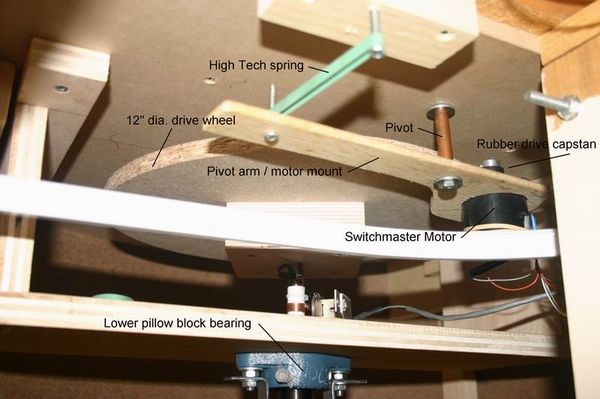
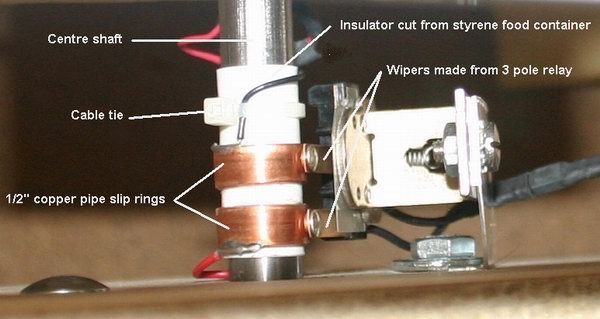
I used the keyway in the shaft to run two wires down to a pair of slip rings which can barely be seen in the picture of the drive parts. Two rings were cut from 1/2″ copper water pipe and insulated from the main shaft. Wipers were added to run on the rings. Being as my layout is DCC, I ran the power feed wires through an auto-reversing circuit. It would be a little easier to connect one rail to the shaft and the other to the pit rail. A simple wiper on the shaft would suffice and no insulating of the slip rings would be necessary.